You are probably thinking that most programmers are using the text-based languages such as HTML, Java, C++ and many more.
However, ladder logic is entirely different because it is made for engineers and electricians to use it, so we cannot compare it with regular computer programming.
The first difference is in perspective, because ladder logic is a graphical programming language and you will need comprehensive knowledge on electric circuits so that you can implement switchgear and back-up generators.
The main reason why ladder logic entered the market is to make it more convenient and intuitive when it comes to programming PLCs, which replaced hardwired relays, and relay logic that most industrial environments used along the way.
You should understand that today’s PACs are including other languages as well as IL, SFC, FBD,and ST, which means that ladder logic, is not the only way to use PLCs.
However, it is one of the most popular ways,and there are numerous benefits of using it due to convenient troubleshooting. Since it is visually based language, it is simple to spot and consider where in rung the logic is problematic, so that you can deal with it and continue with automation.
Since it is similar to relay control ladder diagrams, it will provide to engineers, electricians,and technicians the advantage because they will be able to use it with ease and without additional training and learning.
Ladder Logic Instructions

Even though you can find a hundred instructions that use Ladder Logic, most of them are rarely used, becausethe idea is to create convenient solutions and guidelines that will help you along the way,
You can implement a few of them that you will use repeatedly, and the idea is to focus on essential instructions that will help you understand this particular graphical language.
The idea is to look at some instructions, counters,andtimers so that you can do plenty of things with it. The idea is not to list eachdirection in combination with the technicaldescription so that you can do it yourself and figure out what it is about.
No, we are going to present you examples that will help you use these instructions in real time and real industrial environment. Have in mind that the instructions you will see here are not based on the specific and existing systems.
They are just a description and explanation on what you can do with it when you are in the plant and industrial environment.
In case that you decide to use ladder logic on a real system, it is vital to understand a common sense, to test it entirely and to verify its safety for both personnel and appropriate equipment you are using.
If you wish to learn more on relay logic, we recommend you to check here for more information.
- Relay-Type Instructions
This is one of the most used and most important instruction,and we call it relay instruction. The three most commonly used relay instructions are XIO (examine if open), XIC (investigate if closed) and OTE (output energized).
Have in mind that these three instructions can be compared with the relay coil, normally closed and normally open contact.
If you are a beginner when it comes to electrical circuits, you should understand that ordinarily, open contact means that circuits are disconnected and it will become connected as soon as you activate a trigger device such as relay coil, switch or push-button.
On the other hand, normally closed contact is the complete oppositeanddidmean that circuit is connected and it will disconnect as soon as you trigger the device through the button, relay coil or a switch.
A relay coil is an electromagnetic device that will move contact as soon as current enters and passes through it. The idea is that OTE is energized by using regular open contact. As soon as it gets there, it will contact XIC so that you can place the stop button to release the contact.
Have in mind that Start and Stop buttons are wired to the PLC inputs because if the switch or input fails, it will stay open in overall. These are the reasons why if the input fails, the motor will not run, and everything will immediately stop. Start buttons are wired opposite.
Stop button physical contact is wired to the PLC input so that it can be a final contract that turns it off as soon as you make physical contact with it. If you wish to de-energize the motor, you have to push the stop button, which will break the seal between motor start contact and coil.
On the other hand, if you wish to re-energize the motor, you will have to press the start button while letting go the stop button in overall. By energizing the motor start coil, you will create open contact, while when you close it; you will seal it in again.
You have to be familiar with control circuits especially if you want this to make sense. Check this link: https://automationforum.co/relay-instructions-for-allen-bradleys-plc-ladder-diagram/ to learn more on PLC Ladder diagram and its operations.
- Counters and Timers
The most common instruction after the Relay type is counters and timers. The idea is to do exactly as the name suggests to count and to state the exact time. The timer instructions are TON or Time on Delay.
Have in mind that TON tends to begin timing as soon as run becomes active, and at times up to present value and then it will set the tone bit that you can use as a trigger so that you can deal with another part of the logic.
The timer will be enabled and will begin timing as soon the output is on. In case that you set a preset for 300,000 milliseconds, it means that output will last for that particular time and as a result, it will open XIO, which will interrupt motor start rung.
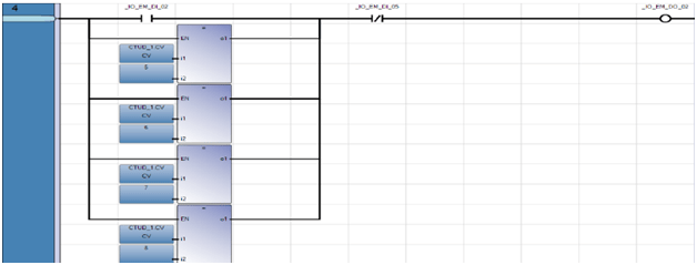
On the other hand, the most common type of counter is Count Up or CTU. If we set the value to 1000, it means that you will have to enable the counter thousand times before the DN bit will complete.
As soon as you enable the CTU, you will be able to CU as a result. The counter will count when the ring goes from false to right, and that means to count up each time output is turned on.

